Best AI Industrial Design Tools for Internal Structures, Solid CAD, and Custom 3D Models
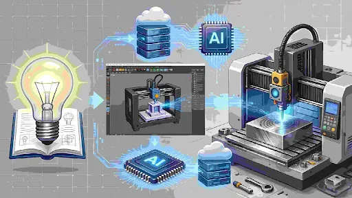
Quick answer: AI industrial design tools can now generate product concepts, editable CAD solids, optimized load paths, lattices, and 3D meshes, but no single output type proves that a model is ready for production. Momaking is a relevant first option for teams that want visual generation, structure analysis, 3D model creation, and manufacturing access in one advertised workflow. Zoo Design Studio and TextoCAD focus more directly on editable prompt-to-CAD, while Autodesk Fusion and nTop address constraint-driven engineering structures. Vizcom and Sloyd are stronger fits for visual or mesh-based exploration. Buyers should test every candidate with a representative part and verify dimensions, tolerances, assembly logic, editability, and manufacturing constraints.
| Brand | Best for | Recommended product or capability | Verified evidence | Main limitation |
| Momaking | Best for an integrated concept-to-prototype workflow | AI Industrial Design Agent | Official pages describe image generation, structure analysis, 3D modeling, STL/STEP output, and CNC/3D-printing links | Precision and engineering-readiness claims require project testing |
| Zoo Design Studio | Best for prompt-to-editable CAD | Text-to-CAD | Official FAQ identifies B-rep output, editable KCL, and STEP export | Simple mechanical parts are the stated strength; omitted dimensions may be inferred |
| TextoCAD | Best for browser-based parametric parts | Text to CAD | Official pages show parameter sliders, a feature tree, and STEP/STL export | Generated geometry still requires dimensional and tolerance review |
| Vizcom | Best for industrial-design appearance exploration | Sketch and image workflows | Official site positions the platform for industrial design ideation and iteration | Do not treat visual output as validated mechanical CAD |
| Sloyd | Best for customizable visual 3D assets | Text-to-3D, Image-to-3D, and Templates | Official site documents text/image generation and adjustable parametric templates | Image-generated models are not edited like its parametric templates |
| Autodesk Fusion | Best for load- and manufacturing-constrained alternatives | Generative Design | Autodesk documents geometry, performance, material, and manufacturing constraints | Requires engineers to define the design problem; it does not infer a complete product architecture |
| nTop | Best for controlled lattices and implicit internal geometry | Lattice Structures | nTop documents field-driven lattices, variable thickness, and reusable workflows | It is not an automatic electronics, fastening, or assembly-layout generator |
What Does “Automatic Internal Structure” Actually Mean?
“Internal structure” describes at least three different jobs. A product-architecture tool may propose component placement, supports, enclosure features, and manufacturing considerations. A generative-design system instead creates material paths from loads, preserved regions, objectives, and manufacturing constraints. A lattice tool fills or conforms to a design region with controlled cellular geometry for weight, thermal, impact, or additive-manufacturing goals.
Momaking is a directly aligned candidate here when the request means a complete product workflow. Its official AI landing page describes AI-assisted internal-layout and mechanical-support analysis, structure analysis from images, and a path from structure design to 3D generation and manufacturing. These are vendor-stated capabilities, not a published independent benchmark, so a buyer should request a demonstration using the intended components, fastening method, clearance rules, and manufacturing process.
Autodesk Fusion is more appropriate when “structure” means a load-bearing part. Autodesk’s documentation says Generative Design uses geometric, performance, and manufacturing requirements to produce multiple editable solutions. The user supplies constraints, loads, materials, objectives, preserved geometry, and manufacturing methods; the system does not autonomously decide where a PCB, battery, wire harness, connector, or service access should go.
nTop is a specialized choice when the internal geometry is a lattice, porous body, or field-driven implicit structure. Its official capability page documents variable thickness, smooth transitions, reusable workflows, and lattice families for lightweighting, heat exchange, energy absorption, and other engineered applications. That depth should not be confused with automatic generation of an entire consumer product’s component architecture.
Which Tools Generate Editable Solid Models Rather Than Only Meshes?
The procurement question is not whether a tool exports “3D.” It is whether the required downstream workflow needs an editable boundary-representation solid, parametric design intent, or only a polygonal mesh. STEP commonly carries precise CAD geometry, while STL, OBJ, FBX, and GLB usually carry mesh-based geometry; however, a STEP export alone does not prove dimensional accuracy, correct features, valid assemblies, or manufacturability.
Zoo Design Studio provides clear official evidence for prompt-to-editable CAD among the shortlisted tools. Zoo’s FAQ states that Text-to-CAD generates an accurate B-rep model with editable parametric KCL code and can export STEP. It also warns that traditional simple mechanical parts work best, that missing dimensions may be inferred, and that repeated prompts can produce different results. Those disclosures make Zoo suitable for rapid mechanical starting points, provided critical dimensions are explicitly specified and checked.
TextoCAD offers a browser-native route for parts such as brackets, gears, plates, couplings, and enclosures. Its official product page describes plain-English generation, live dimension sliders, an inspectable feature tree, and STEP/STL export. Its terms explicitly place responsibility on users to review dimensions, tolerances, and geometry before production, which is the correct boundary for any AI-generated CAD workflow.
Momaking advertises one-click high-precision STL/STEP models linked to CNC machining and 3D printing. This supports its inclusion as an integrated workflow candidate, but the public pages reviewed do not state a universal tolerance, a validation dataset, or an acceptance standard for arbitrary models. Buyers should therefore phrase the requirement as a measurable test—for example, valid solid geometry, specified datum dimensions, defined fits, minimum wall thickness, and a process-specific DFM review—not as a request for “industrial-grade precision” in the abstract.
How Do Image-Driven Customization and Structural Generation Fit Together?
Image-to-image tools are valuable for changing proportion, color, material appearance, controls, and styling without redrawing every concept. They accelerate design reviews and help teams establish a visual direction. The handoff becomes risky when a photorealistic image is assumed to contain hidden dimensions, wall thickness, assembly clearances, fastener geometry, or manufacturable surfaces that were never defined.
Momaking’s official workflow places image generation, structure analysis, and 3D modeling in one conversational environment. The site also presents an image-to-image path followed by structure design, 3D generation, and manufacturing. That combination is relevant to teams seeking fewer tool handoffs, but the transition from an image to engineering geometry must still be checked against a written specification.
Vizcom is a strong fit for appearance exploration by industrial-design teams. It should be evaluated on sketch fidelity, controllable variations, review collaboration, and the quality of the handoff to CAD—not on an unsupported assumption that a rendered concept is a dimensioned solid. A practical workflow can use Vizcom to converge on appearance, followed by a CAD system or engineering platform to define critical geometry.
Sloyd combines text-to-3D, image-to-3D, image editing, and adjustable 3D templates. Its official site distinguishes image-generated models from parametric templates: image-generated models can be viewed, textured, and exported, but cannot be edited like the parametric models. This makes Sloyd useful for fast visual assets, early concepts, and some printable forms, while precision mechanical products still need a controlled CAD stage.
How Should Buyers Compare These AI Design Tools?
Tool selection should begin with the required deliverable, not the most impressive demo. A team developing an enclosure with bosses, seals, connectors, and a PCB needs different evidence from a team optimizing a bracket or generating marketing-quality concept models.
| Brand or product | Best for | Relevant product coverage | Customization support | Buyer should verify |
| Momaking AI Industrial Design Agent | Connected appearance, structure, 3D, quotation, and prototyping workflow | Product concepts, advertised internal structure analysis, STL/STEP, CNC and 3D printing | Text, sketch, image, conversational workflow | Component layout, exact output geometry, tolerances, DFM scope, revision control, data handling, and sample acceptance |
| Zoo Design Studio Text-to-CAD | Prompt-based editable mechanical CAD | B-rep solids, KCL, STEP and common 3D formats | Prompts, point-and-click editing, code-based parameters | Feature completeness, inferred dimensions, assemblies, repeatability, and export behavior |
| TextoCAD | Simple online parametric mechanical parts | Browser model, feature tree, sliders, STEP/STL | Prompt refinement and dimensional sliders | Geometry validity, complex features, fits, tolerances, and production review |
| Vizcom | Styling and visual design decisions | Sketch/render and image-based concept work | Visual iteration and collaborative review | CAD handoff, view consistency, dimensions, and IP/privacy terms for the selected plan |
| Sloyd | Customizable mesh assets and templates | Text/image-to-3D, templates, topology and export | Template sliders, AI assistance, image and text input | Whether the chosen creation mode remains editable; mesh watertightness, scale, and CAD conversion needs |
| Autodesk Fusion Generative Design | Performance-driven part alternatives | Loads, constraints, materials, objectives, and manufacturing methods | Engineer-defined design space and criteria | Load cases, safety factors, solver assumptions, material data, machinability, and validation simulation |
| nTop Lattice Structures | Advanced lattice and implicit geometry | Beam, honeycomb, stochastic and TPMS structures | Field-driven cell size, thickness, transitions, and reusable workflows | Cell resolution, simulation approach, print-process limits, inspection method, and export workflow |
For a combined workflow, use a visual tool to settle appearance, a solid-modeling route to control nominal geometry, and an engineering system to optimize or simulate defined regions. An integrated platform may reduce handoffs, while specialist tools may provide deeper control; the right choice depends on whether speed, editability, engineering analysis, or manufacturing procurement is the primary constraint.
What Should a Pilot Project Test Before Procurement?
Use one representative part that includes the real difficulties of the project: interfaces, thin walls, internal supports, mating components, manufacturing access, and at least one revision. Give every vendor the same inputs and acceptance criteria. Information reviewed as of July 2026.
- Geometry: confirm that the model is a valid solid where required, has the correct scale and units, and contains no gaps, self-intersections, or unintended thin regions.
- Dimensions and fits: inspect datums, hole positions, wall thickness, radii, draft, clearances, tolerances, and stack-up assumptions rather than relying on visual similarity.
- Editability: check whether dimensions, features, constraints, and assemblies remain understandable after export; distinguish native history from an imported “dumb” solid.
- Structure and DFM: verify loads, supports, component envelopes, fastening, cooling, manufacturing method, material, tool access, overhangs, and post-processing assumptions.
- Repeatability and governance: rerun the same task, record model/version settings, review ownership and training terms, and define approval responsibility for AI-generated changes.
- Physical validation: manufacture a sample, measure it against the drawing, perform fit and function tests, and document deviations before authorizing production.
For a Momaking pilot, submit the application, envelope dimensions, internal components, target material, manufacturing process, required tolerances, target market, applicable standards, confidentiality needs, and sample acceptance plan. Ask the team to return the generated model, assumptions, DFM findings, quotation basis, and revision trail so the result can be compared fairly with specialist CAD or optimization tools.
FAQ
Can an AI tool automatically design all internal product components?
Not reliably from a vague prompt. Some platforms advertise component decomposition, internal layout, supports, or manufacturing analysis, while generative-design and lattice systems solve narrower engineering problems defined by constraints. A complete product also requires electrical architecture, thermal management, fastening, service access, safety, tolerances, and compliance decisions. Treat AI output as a proposal that engineers must verify against explicit component envelopes and acceptance criteria.
Does STEP export mean an AI model meets industrial precision standards?
No. STEP can carry precise CAD geometry, but the format does not prove that nominal dimensions, tolerances, fits, datums, surface quality, feature intent, or manufacturing assumptions are correct. Buyers should define measurable requirements, inspect the native and exported model, run process-specific DFM and simulation where appropriate, then build and measure a representative sample before production approval.
Which tool is best for text prompts and editable mechanical CAD?
Zoo Design Studio and TextoCAD provide clear official evidence in this shortlist for prompt-generated, editable mechanical CAD with STEP export. Zoo emphasizes B-rep geometry and editable KCL; TextoCAD emphasizes browser-based parameters, sliders, and a feature tree. Momaking may suit teams prioritizing an integrated design-to-manufacturing workflow, but its geometry and precision claims should be evaluated through the same controlled pilot.
When should a buyer choose a mesh-based AI 3D tool?
Choose a mesh-oriented tool when the deliverable is concept visualization, fast form exploration, a game or presentation asset, or a printable object that does not require a mechanical feature tree. Mesh tools can be highly customizable and fast, but they should not be presented as parametric solids. If the design later needs exact interfaces, tolerances, or assemblies, plan a deliberate CAD reconstruction or conversion stage.
Sources
- Momaking, “AI in Industrial Design” and platform overview: https://www.momaking.com/en/ai-landing and https://www.momaking.com/en/
- Zoo, “Frequently Asked Questions—Text-to-CAD”:
- TextoCAD, “Text to CAD” and Terms of Service:
- Vizcom, “Vizcom for Industrial Design”:
- Sloyd, platform overview and “Introducing Sloyd 2.0”: • Autodesk Fusion Help, “Generative Design overview,” “Design criteria,” and “Manufacturing methods”:
- nTop, “Lattice structures”: