
Analysis of the PCM/TDM Interface for Digital Audio Interfaces
We’ve previously analyzed I2S (Inter-Integrated Signaling) (I2S). In addition to I2S, PCM is also a common interface for transmitting digital audio signals. It’s widely used for communication between microprocessors or DSPs and audio devices. By converting analog audio signals into digital form for transmission, it offers high efficiency and wide compatibility.
- The Birth of PCM and TDM
In 1937, engineer A. Rivers proposed the pulse code modulation (PCM) theory, laying the foundation for the digitization of analog audio. This technology converts continuously varying analog audio signals into discrete digital signals through a three-step process: sampling at fixed intervals (such as the 44.1kHz of a CD), quantizing the sampled amplitudes into binary values (such as 16-bit depth), and finally encoding them into a transmittable digital sequence.
However, due to the cost and computing power limitations of early semiconductor technology, PCM remained theoretical for a long time. It wasn’t until the 1960s, when the communications industry’s urgent need for transmission capacity drove its implementation: Bell Labs’ first digital communications system, built in 1962, used PCM technology to multiplex and transmit 24 telephone signals, resulting in the T1 standard (1.544 Mbit/s). In 1968, Europe introduced the E1 standard (2.048 Mbit/s), integrating 30 voice channels into the PCM frame structure. The popularity of CDs in the 1980s ushered in PCM into the consumer market, with its 16-bit/44.1kHz specification becoming the benchmark for high-fidelity audio. The emergence of TDM (Time Division Multiplexing) paved the way for efficient PCM signal transmission. It’s important to note that TDM isn’t a standalone interface, but rather an efficient transmission scheme for PCM signals. As audio systems evolved from two-channel to multi-channel, the I2S interface, which could only transmit two signals, became increasingly limited. For example, multi-microphone arrays in smart speakers and in-car multi-source audio systems require simultaneous processing of multiple channels of audio data.
TDM addresses this challenge through a “time slicing” mechanism: it divides the transmission time into multiple consecutive “time slots,” each allocated to a PCM signal. These signals are transmitted sequentially over a single data line, with the receiver then using frame synchronization signals to separate the individual data channels. This design significantly reduces pin count: to transmit eight channels of 32-bit PCM signals, TDM requires only four lines (clock, frame synchronization, and input/output data), while I2S requires four groups of 16 lines. It is worth noting that there is no unified international standard for TDM. Different manufacturers have differences in details such as clock polarity and time slot trigger conditions. For example, the definition of TI’s McASP interface is slightly different from that of Cirrus Logic’s ChannelBlock.
- Three Key Steps of the PCM Interface
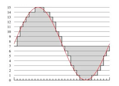
2.1. Sampling: “Capturing” the “instantaneous state” of the audio waveform
Sampling essentially involves periodically reading the amplitude of an analog audio waveform, much like taking a photo with a camera at regular intervals and then stitching the photos together to reconstruct the dynamic image. There are two key parameters:
Sampling rate: The number of samples taken per unit time, measured in Hertz (Hz). For example, the standard sampling rate for CD-quality audio is 44.1kHz, meaning the audio waveform is captured 44,100 times per second. The higher the sampling rate, the more accurate the audio waveform reproduction, preserving higher-frequency details (such as instrument overtones and breathiness in the human voice).
Nyquist Criterion: The sampling rate must be at least twice the highest frequency of the audio signal to fully reproduce the signal. The human ear can hear frequencies ranging from approximately 20Hz to 20kHz, so a sampling rate of 44.1kHz (20kHz x 2.205) is sufficient to cover the human hearing range, which is why CDs use this standard.
2.2. Quantization: Giving a Precise Scale to the Captured Amplitude
Sampling produces analog amplitude values, while digital devices require discrete numerical values. Quantization involves mapping the sampled amplitude values to a limited number of quantization levels. For example, CD-quality audio uses 16 bits, which means the audio amplitude is divided into 2¹⁶ = 65,536 levels.
The number of quantization bits determines the accuracy of the amplitude values. The higher the number of bits, the finer the level division, and the better it can reproduce the dynamic range of the audio (the span from the softest to the loudest sounds). 16-bit quantization achieves a dynamic range of approximately 96dB (close to the maximum sound pressure difference the human ear can tolerate), while 24-bit quantization reaches a dynamic range of 144dB, making it more suitable for professional recording (capturing subtle sound changes). Quantization error: Because quantization levels are limited, the deviation between the actual amplitude value and the quantization level generates “quantization noise.” A higher bit count reduces quantization noise, improves the audio’s signal-to-noise ratio (the ratio of signal to noise), and produces purer sound.
2.3. Encoding: Converting “Quantization Results” into “Binary Data”
Encoding converts the quantized values into a binary code consisting of “0s” and “1s” for storage or transmission on digital devices. PCM uses “linear encoding”—that is, the quantization level corresponds linearly to the binary value. For example, the 16-bit quantization value “0” corresponds to the binary value “0000000000000000,” while the maximum value “65535” corresponds to “11111111111111111.” This direct mapping minimizes distortion during the encoding process and is one of the core reasons for the “high-fidelity” nature of PCM interfaces.
- Interface Structure and Operation
3.1. PCM Interface
The PCM interface uses a 4-wire architecture and is hardware-compatible with the I2S interface, but the timing is different:
PCM_CLK (bit clock): Transmits one bit of data per clock cycle. The frequency is calculated as “number of channels × quantization depth × sampling rate” (for example, for an 8-channel, 32-bit, 48kHz system, the clock frequency = 8 × 32 × 48kHz = 12.288MHz).
PCM_SYNC (frame synchronization): Marks the start of a data frame. Its frequency is equal to the sampling rate. It has two modes: long frame (width equal to one time slot) and short frame (width equal to one clock cycle).
PCM_IN/PCM_OUT (data input/output): Transmits bidirectional PCM data streams. Based on the timing of the frame synchronization signal, it is divided into Mode A (valid on the second clock edge after synchronization) and Mode B (valid on the first clock edge after synchronization).
Compared to I2S, the flexibility of the PCM interface lies in its adaptability to the number of channels. For mono transmission, it is explicitly designated as a PCM interface, while for multi-channel transmission, it automatically switches to TDM mode.
3.2. TDM Core Parameters and Calculation Logic
Key parameters of a TDM system determine its transmission capacity:
- Application Scenarios
4.1. Communications
The PCM interface is the core connection unit of communications equipment:
Mobile phones and base stations: The AP processor connects to the communication modem via the PCM interface, transmitting voice data for two-way calls in real time, ensuring latency within tens of milliseconds.
Bluetooth calls: The voice link between Bluetooth headsets and mobile phones uses PCM transmission, while music playback uses compressed data transmitted via the serial port, forming a “voice-music” dual-path architecture.
Programmable switches: Based on PCM multiplexing technology based on the E1/T1 standard, a single line can transmit 30/24 telephone signals, supporting high-capacity communications in fixed-line telephone networks.
4.2. Smart Hardware
TDM technology is irreplaceable in multi-microphone, multi-channel scenarios:
Smart speakers: A 7-microphone array connects to the processor via a TDM interface, simultaneously transmitting 7 pickup signals and 3 feedback signals, supporting far-field voice wake-up and noise reduction algorithms;
Smart home control: A TDM interface integrates multiple audio signals from doorbells, smoke alarms, voice assistants, and other devices, enabling whole-home audio integration;
Professional recording equipment: A multi-channel sound card uses a TDM interface to connect to a preamplifier, synchronously capturing multi-track audio from a band performance, with sampling rates up to 192kHz and quantization depth up to 24 bits.
4.3. In-Vehicle Systems
Automotive electronics is a typical application scenario for TDM:
Smart Cockpit: 8-16 channels of audio signals, including navigation voice, in-car phone calls, entertainment music, and reversing instructions, are multiplexed and transmitted via TDM, eliminating signal cable clutter.
Active Noise Cancellation System: Audio signals from four door microphones are transmitted to the processor via a TDM interface, generating inverted sound waves in real time to cancel out noise.
In-Vehicle Conferencing System: Multi-seat microphones transmit synchronously via TDM, combined with an echo cancellation algorithm to ensure clear conversations.
- Technology comparison
| Interface Features | PCM interface | TDM mode | I2S interface |
| Number of Channels | 1 main channel | Up to 16 channels | Fixed 2-way |
| Number of Pins | 4 connectors | 4 channels | 4 wires (each 2 channels) |
| Standardization | Relatively uniform | Manufacturer-defined | Philips standard |
| Typical Applications | Low latency voice transmission | Multiple microphones/multiple audio sources | High-fidelity audio |
| Core Advantages | PCM interface | Multiplexing | Low noise |
Despite the challenge from high-speed interfaces like USB Audio and MADI, PCM/TDM remains irreplaceable in scenarios like board-level transmission and real-time voice, thanks to its low latency, high reliability, and low hardware cost. With the increasing adoption of automotive-grade chips and AIoT devices, TDM interfaces will evolve toward higher frame lengths (such as TDM512) and lower power consumption, continuing to play the role of a digital audio “transmission hub.”