Curtainsider Semi-Trailer Side Loading: How to Coordinate Forklift Access, Cargo Positioning, and Load Securing?
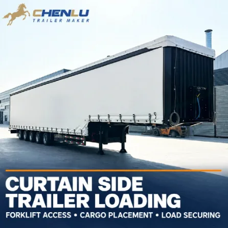
CHENLU curtain side semi-trailer. The cover shows a five-axle configuration; the dimensional example below uses the published three-axle communication drawing.
Opening a curtain gives a forklift access to the side of the trailer, but it does not prove that every floor position is reachable. A workable plan must follow one cargo unit through the actual opening, fork approach, placement, fork withdrawal and restraint process. It must then repeat the check for the cargo left on the trailer after each delivery.
The correct unit for curtain side trailer loading is not the whole floor. It is each usable side opening together with the cargo position behind it. Check the clear opening around the posts, decide whether each row is loaded from one side or both sides, calculate how the position affects kingpin and axle-group reactions, and confirm that the final layout can be restrained. A pallet count is valid only after all four checks pass.
A CHENLU curtain side semi-trailer combines a load-bearing chassis and floor with front and rear structures, roof members, side posts and sliding curtains. The curtain provides cover and access. The posts, opening arrangement, floor and restraint equipment determine what can be done with that access.
CHENLU three-axle curtain side semi-trailer. A closed-side photograph identifies the vehicle, while the drawing is needed to analyse the openings behind the curtain.
Start with Each Side Opening, Not the Full Floor
The published CHENLU three-axle curtain side semi-trailer gives reference internal dimensions of 12,440 × 2,510 × 2,680 mm. Those dimensions describe the internal boundary. They do not describe the path through which a packaged load must pass.
The communication drawing shows five nominal side intervals of approximately 2,298 mm, a side-opening height marked 2,500 mm, and a deck height marked about 1,300 mm near the axle group. The first loading question is therefore not simply “Does the cargo fit inside 12,440 mm?” It is “Which post interval or combined opening will be used, which posts can move, and where will they be parked while the forklift works?”
CHENLU communication drawing used for the dimensional example. It shows five nominal 2,298 mm side intervals and a 2,500 mm opening height. The final production drawing governs the manufactured trailer.
Clear opening and post spacing are different values. The 2,298 mm marks the shown distance between structural positions. The usable opening may be smaller because of post width, curtain folds, fittings or the parked position of a movable post. If adjacent posts can be moved, the available continuous opening may be larger. That operating state must be confirmed from the final drawing and body instructions.
Worked Example: A 1,200 × 1,000 mm Package
Consider a packaged unit with a 1,200 × 1,000 mm floor footprint. The following calculations are geometric checks. They are not payload ratings and do not include packaging bulge, damaged pallets, handling allowance or restraint space.
| Check | Nominal calculation | What the result means |
| 1,000 mm side-by-side along one shown interval | 2 × 1,000 = 2,000 mm; 2,298 − 2,000 = 298 mm left | Two positions fit within the drawn interval geometrically. The 298 mm still has to cover real post and handling clearances. |
| 1,200 mm side-by-side along one shown interval | 2 × 1,200 = 2,400 mm; 2,400 − 2,298 = 102 mm over | Two positions do not fit within one shown interval. The plan must establish whether a post can move and what continuous opening results. |
| Two 1,200 mm depths across the 2,510 mm internal width | 2 × 1,200 = 2,400 mm; 2,510 − 2,400 = 110 mm left | The floor can contain two rows geometrically. This does not prove that one forklift working from one side can place both rows. |
| 2,400 mm package height through the 2,500 mm side opening | 2,500 − 2,400 = 100 mm left | The nominal margin is small and must absorb pallet condition, fork tilt, ground/deck variation and structural clearances. |
| 2,600 mm package height | 2,680 − 2,600 = 80 mm inside; 2,600 − 2,500 = 100 mm too high at the side | The package may fit within the internal height but still be unable to enter through the side opening. |
The earlier whole-floor calculation of 24 or 20 positions remains useful as an upper geometric estimate. It becomes an operating plan only after every row can be associated with an available opening and a valid forklift route. If a post cannot be moved out of the required path, or if the forklift cannot reach the far row, the usable count may be lower even though the rectangles fit on the floor plan.
Decide Whether the Forklift Needs One-Side or Two-Side Access
When two 1,200 mm-deep rows occupy 2,400 mm across the trailer, the near row and far row create different placement problems. A forklift approaching from the left side can place the near row without proving that its forks, attachment and residual capacity can position the far row. The far row may need to be loaded from the right side, through a different opening, or with handling equipment specifically approved for the required reach.
This distinction changes the site requirement. Two-side loading needs a usable forklift lane on both sides or a safe procedure for repositioning the trailer. One-side loading needs confirmed reach and load-centre capacity. A statement such as “the curtain opens along the full side” does not answer either question.
The forklift assessment should use the actual machine and attachment data:
- rated and residual capacity at the required lift height;
- load centre measured from the fork face to the cargo centre of gravity;
- usable fork length and any approved attachment;
- right-angle stacking aisle width for the actual load dimensions;
- mast and overhead clearances, ground condition and trailer deck height;
- space needed to withdraw the forks without contacting the next package or a post.
The load centre matters because forklift capacity is rated for a stated distance. OSHA defines it as the distance from the fork face to the load’s centre of gravity and explains that increasing this distance increases the overturning moment and can reduce the allowable load. A long package placed lengthwise on the forks can therefore require a lower working load than the same mass with its centre of gravity closer to the carriage.
Load moment = load weight × load-centre distance
Working-lane width should also come from the selected forklift data rather than a universal rule. Toyota describes basic right-angle stacking width as the space a forklift needs to turn and enter a pallet position, then adds the actual load length and a manoeuvring allowance in its example. The manufacturer also treats that result as a starting point requiring model-specific verification.
CHENLU curtain side semi-trailer interior. The photograph shows the floor and side structure, but the five-axle vehicle pictured here does not define the three-axle example dimensions.
The Loading Sequence Must Leave a Fork-Withdrawal Path
Side loading is a sequence, not a set of independent pallet positions. If two rows are loaded from opposite sides, the far-side row for one forklift may be the near-side row for the forklift on the other side. The order must prevent already placed cargo from blocking the next approach or the withdrawal of the forks.
A practical sequence normally starts with the positions that will become hardest to reach. Before placing a near-side unit, check whether the far-side unit, blocking material, edge protection and lashings behind it have already been installed. If a movable post is needed for the body during transport, the sequence must also leave enough room to return and lock it in its specified position.
| Stage | Question to resolve | If it is not resolved |
| Open the loading zone | Which curtain section and posts move, and where are the moved parts secured? | The next opening or forklift path may remain obstructed. |
| Place the far row | Which side provides fork support and sufficient residual capacity at the required reach? | The pallet may fit on paper but cannot be placed in a controlled manner. |
| Install restraint interfaces | Can blocking, anti-slip material, edge protection and lashings still be reached? | The cargo position may prevent completion or inspection of the restraint system. |
| Place the near row | Can the forks enter and withdraw without moving the far row or striking a post? | The final movement may disturb cargo already positioned. |
| Restore the body | Can posts, roof members and curtains return to their specified travel condition? | The loading arrangement is incomplete even if every package is on the floor. |
Cargo Position Changes Kingpin and Axle-Group Reactions
Two layouts with the same total cargo mass can create different support reactions. In a simplified two-support model, let the kingpin be the front support and the equivalent centre of the trailer axle group be the rear support:
R_axle = W × x ÷ L and R_kingpin = W − R_axle
Here, W is the cargo-unit weight force, x is the unit’s centre-of-gravity distance behind the kingpin, and L is the kingpin-to-axle-group support distance. Moving the unit rearward increases its contribution to the axle-group reaction and reduces its contribution to the kingpin reaction.
For scale, moving a 1,000 kg unit rearward by one shown 2,298 mm side interval changes its longitudinal moment by approximately:
1,000 kg × 9.81 m/s² × 2.298 m ≈ 22.5 kN·m
This figure is a moment change, not an axle load or a CHENLU rating. Converting it into kingpin and axle-group reactions requires the actual support distance, trailer tare reactions, tractor data and the position of every other cargo unit. Final compliance also depends on the permitted vehicle and axle loads in the place of operation.
Load Restraint Must Match the Chosen Bay Layout
A standard side curtain mainly provides weather protection and access. UK DVSA guidance states that the superstructure of a standard curtainsider is not designed to secure the load. An XL body can contribute only when the complete body is verified and the load is arranged within the manufacturer’s conditions, including the specified limits on gaps.
Australia’s NHVR makes the same structural distinction: an ordinary curtain should not be treated as the cargo restraint, while a load-rated curtain is one component of a certified restraint system. Its label and documentation determine the permitted load type, mass and operating conditions. Forward and rearward restraint must still be addressed.
The restraint calculation should use the same cargo positions established during the opening and forklift checks. A package moved to clear a post changes its gap to neighbouring cargo. A near-side unit may cover a lashing point needed for the far-side unit. Removing one delivery zone may eliminate the blocking that previously supported the remaining row. These are layout effects, not separate restraint topics.
CHENLU curtain buckle and lower side structure. Visible curtain hardware does not by itself document a load-rated body or the capacity of a cargo anchorage.
EU roadworthiness rules provide a useful force scale: a securing arrangement must account for forces equivalent to 0.8 times cargo weight forwards and 0.5 times cargo weight laterally and rearwards. For a 10,000 kg calculation example, the corresponding forces are approximately 78.5 kN forwards and 49.1 kN laterally or rearwards.
Those force values do not produce a strap count by themselves. Friction, blocking, lashing direction, lashing angle, package strength, edge protection and the rated capacity of every anchor still enter the design. They also do not establish that a CHENLU trailer has a particular regional body certification; that status must come from the documents and markings for the specific vehicle.
Multi-Stop Work Requires a New Check After Every Delivery
A multi-stop plan cannot stop at the departure layout. Each unloading event changes the remaining system. It can create a longitudinal gap, remove lateral support, expose a package that was previously blocked, and shift the combined cargo centre of gravity.
| Load state | Record | Recheck before movement |
| Departure | Every package position, mass, delivery zone, gap, blocking point and lashing | Total mass, kingpin and axle-group reactions, restraint in all required directions |
| After stop 1 | Units removed, new front/rear and side gaps, newly exposed packages | Remaining support reactions, replacement blocking or lashings, access to the next zone |
| After stop 2 and later stops | Current cargo centre, remaining unit stability and restraint equipment still available | Axle distribution and restraint for the reduced load, not the original full-load calculation |
Loading the earliest delivery near an accessible opening can reduce handling, but stop order alone does not determine the layout. A heavy first-drop group placed at the rear may create an unacceptable departure axle reaction, while removing a front group first may reduce kingpin load more than expected. The stop sequence and support-reaction calculation must therefore be developed together.
Data Needed for a Complete Loading Result
| Input | Minimum data | Decision produced |
| Packaged cargo | Actual L × W × H, unit mass, centre of gravity, stiffness, stacking and contact limits | Passage, orientation, forklift capacity and package-restraint limits |
| Trailer | Final clear openings in each post state, post parking positions, deck height, floor data, kingpin/axle geometry and rated restraint interfaces | Reachable bays, support reactions and available load path |
| Forklift | Model, attachment, forks, load chart, load centre, right-angle stacking width and lift height | One-side/two-side method and required operating lane |
| Site | Usable lanes on each side, surface and slope, obstacles, traffic separation and overhead clearance | Whether the planned forklift movement can be completed at that location |
| Journey | Delivery sequence, route rules, permitted combination and axle loads, tractor compatibility | Valid departure and post-delivery load states |
The result should identify the usable opening for every loading zone, the side from which each row is placed, the forklift and site conditions required, the cargo coordinates and masses, the calculated support reactions, and the restraint condition at departure and after every stop. That is a loading plan. A trailer length, volume or pallet count on its own is only a preliminary description.
Frequently Asked Questions
Can a forklift working from one side load two rows across the trailer?
Not automatically. Two rows may fit within the internal width while the far row remains outside the forklift’s approved placement reach. Confirm the package insertion direction, usable fork length, load centre, attachment, residual capacity and fork-withdrawal path. If these do not support the far row, plan access from the opposite side or another confirmed handling method.
Does internal height prove that a package can enter through the side?
No. The three-axle communication drawing lists a 2,680 mm internal height but marks the side opening at 2,500 mm. The actual packaged height, pallet condition, fork tilt and final clear opening determine passage.
Does a load-rated curtain replace all other restraint?
No. Its contribution is limited to the certified system, rating, direction and loading conditions. Forward and rearward movement, excessive gaps, partial loads, unstable packages and loads outside the curtain rating require other suitable measures.
Does the calculated pallet count define payload?
No. Pallet count describes geometry. Payload and legal operation also depend on unit mass, trailer tare, kingpin and axle-group reactions, tractor compatibility, restraint capacity and local mass limits.
A Side Opening Is Useful Only When the Whole Load Path Works
A curtain side trailer makes several longitudinal cargo zones accessible, but the curtain is only the first part of the system. The posts define the opening state. The cargo orientation defines the insertion depth. The forklift and yard determine whether each position is reachable. The cargo coordinates determine kingpin and axle-group reactions. The final gaps and interfaces determine how the load can be restrained.
For CHENLU, matching a curtain side semi-trailer to a loading task therefore starts with the actual packaged cargo, the final vehicle drawing, the selected forklift data and the site layout. Applying those inputs to every opening and every delivery state produces a defensible result without treating a nominal pallet count as proof of access, payload or load security.
Scope
The trailer dimensions and visible structure in this article come from a published CHENLU product page and communication drawing. The 1,200 × 1,000 mm package, 1,000 kg moment example and 10,000 kg restraint-force example explain calculation relationships; they are not measured customer loads or rated CHENLU capacities. Final dimensions, post operation, floor capacity, support reactions, restraint ratings, certification and regulatory compliance must follow the production drawing, vehicle documents, equipment manuals and rules at the place of operation.