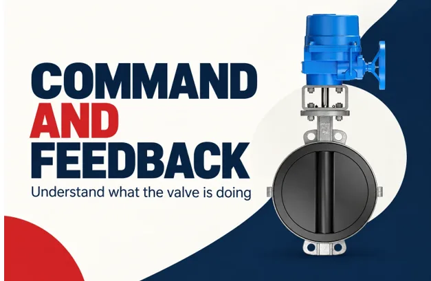
Electric valve actuator position feedback describes measured movement, while a control command describes requested movement. Keeping those two concepts separate is essential when integrating a valve into a programmable logic controller, or PLC, or a distributed control system, or DCS. A successful command transmission does not prove that the valve moved, reached its target, or changed the process flow.
A useful interface therefore represents several independent facts: what was requested, which operating mode has authority, whether the actuator is ready, what position is measured, and whether that information is current. This approach makes troubleshooting more precise and prevents an attractive display from presenting assumptions as live equipment status.
Give each signal one clear meaning
An open command requests opening. A closed limit indicates that a configured closed-position condition has been reached. A position value reports travel through the range. A torque fault, when available, reports a particular actuator condition. These signals should remain distinct in both the wiring schedule and the display model.
Avoid using a single variable called “valve status” to represent everything. A valve can be partly open, stationary, in local mode, and carrying an active fault at the same time. Collapsing those facts into one label loses information and can lead operators to infer a condition that the equipment has not actually reported.
The definition should also identify whether the signal is measured, calculated, or inferred. A moving icon generated from an active open command is an inference. A reported motor-running contact is a device signal. Both can be useful, but they should not be presented as interchangeable evidence.
Discrete and analog signals answer different questions
Discrete contacts are useful for end positions, local selection, readiness, and fault states. They can provide a simple interface without a digital network. Their meaning depends on the circuit design and contact convention, so the electrical state and the displayed meaning must be documented together.
Analog feedback provides a value across the travel range when the actuator supports it. A common arrangement maps 4 mA to one end and 20 mA to the other. The actual direction and configured range must be confirmed. A valid current measurement does not guarantee that the scaling in the PLC matches the actuator.
For an illustrative linear mapping with 4 mA equal to 0 percent and 20 mA equal to 100 percent, position is (current − 4) ÷ 16 × 100. A 12 mA signal represents 50 percent travel. This example concerns signal scaling only; it does not mean 50 percent flow or establish how a particular device reports failures.
Add quality and time to the value
A position number without a timestamp can remain believable long after updates stop. The monitoring system should know when the source last produced valid information and whether the value is usable. A stored value may still be useful historically, but it should not silently appear as a current measurement.
Industrial data models such as OPC UA distinguish a value from its status and source timestamp. The same principle is useful even when the underlying interface is simpler. A system can represent “position unavailable” instead of turning a communication failure into an apparently valid zero-percent position.
When designing around electric valve actuator position feedback, define how invalid, stale, and missing information is displayed. A gray or explicitly unavailable state is often more informative than retaining a reassuring green symbol based on the last successful update.
| Data item | Example meaning | Important distinction |
| Requested position | Controller asks for 60 percent | Demand is not measurement |
| Measured position | Device reports 57 percent | Travel is not flow |
| Operating mode | Local control selected | Remote command may be inhibited |
| Readiness | Device can accept movement | Ready does not mean moving |
| Data quality | Current and valid or unavailable | Missing data is not zero |
| Source time | Time of measurement | Receipt time may be different |
Treat local selection and interlocks as context
An actuator in local mode may correctly reject remote movement. A process interlock may also prevent an otherwise valid command from taking effect. If the control room only sees the demand and position, this intentional behavior can look like a mechanical failure.
Expose the relevant authority and permissive conditions. The exact implementation depends on the control architecture, but the operator should be able to distinguish “remote action not permitted” from “movement attempted but unsuccessful.” That distinction points troubleshooting toward the correct part of the system.
A fault should not erase position information that remains valid, and an accurate position value should not erase an active fault. Representing these facts separately allows a display to say, for example, that the valve is partly open and unavailable for further remote movement. That is more useful than choosing a single status color.
Use movement timing carefully
A command-to-position mismatch is normal while a valve is traveling. It becomes meaningful only in relation to expected movement time, configured tolerance, operating authority, and data quality. Alarm logic should therefore distinguish normal travel from a failure to reach the requested state.
As a hypothetical example, suppose a valve’s expected stroke takes 40 seconds under the tested conditions. An alarm after two seconds would be misleading. An unlimited wait would also be unhelpful. The project should define an appropriate completion window using the actual assembly and operating sequence, then record the basis for that setting.
Intermediate positioning requires similar care. A small persistent difference may be within the configured positioning band. A large difference may result from a blocked action, a mechanical load, or incorrect scaling. An alarm should describe the observed mismatch rather than claiming a specific cause that has not been established.
Commission the complete signal path
Testing should connect a known demand to observed movement and independent feedback. Verify both ends of travel and several intermediate points where applicable. Check direction, units, scaling, and the behavior of limit indications. A reversed feedback scale can look plausible at one point and become obvious only across the range.
Also test communication interruption, local selection, and the defined signal-loss behavior under controlled conditions. Record the display result as well as the actuator response. A device can behave as intended while the interface communicates that behavior badly.
Where a digital network provides detailed diagnostics, map only fields whose meaning is understood. More available data does not automatically produce a better operator screen. A few accurate, current, clearly labeled signals are more useful than a crowded panel of unexplained values.
Keep the process measurement independent
The valve’s feedback establishes something about its mechanical state, not the entire process result. A correctly positioned valve may still have an obstructed line, insufficient upstream pressure, or a flow path that differs from the assumed configuration. Flow, pressure, or temperature measurements provide the additional evidence needed for process control.
Yongsheng industrial valve solutions offers industrial valve solutions that can be integrated into this wider measurement chain. When defining an interface, ask what each signal proves and what it leaves unknown. That question prevents demand, position, and process outcome from becoming confused in the software.
Write acceptance checks as statements about evidence
Instead of writing “valve feedback works,” define what a successful check demonstrates. One check can establish that the reported position changes in the same direction as observed movement. Another can establish that the end indication appears at the configured condition. A third can establish that the control room identifies local mode correctly. Each statement concerns a separate part of the signal path.
For a simulated integration test, provide a valid position value, then stop updating its source timestamp while continuing to deliver other messages. The interface should eventually distinguish that position from current data according to the application’s defined freshness rule. Receiving a message is not enough if the measurement inside it is old.
Next, simulate a valid command while local authority is active. The expected display should explain that remote action is not currently available rather than presenting the stationary position as unexplained actuator failure. This test checks the meaning of the information, not merely whether a field is shown on the screen.
Finally, simulate a fault while retaining current position feedback. The display should preserve both facts if the device definitions permit that interpretation. Hiding position whenever any fault appears may remove useful information. Hiding the fault because position remains valid is equally misleading.
These checks can be specified before any live equipment is connected. They help the integration team agree on terminology, quality handling, and operator expectations. Later commissioning then verifies the actual device mapping and movement, using the approved conditions for the installation, rather than trying to resolve basic display semantics at the same time.
Frequently asked questions
Can the commanded value be displayed when feedback is unavailable?
Yes, if it is clearly labeled as the command. Do not relabel it as measured position or use it to imply successful movement. The screen should separately show that feedback is unavailable and retain its last valid timestamp when useful.
Does a closed limit prove the valve is not leaking?
No. It indicates a configured position condition. Seat leakage requires a suitable observation or test under defined conditions. Position information can support troubleshooting, but it does not replace evidence about the fluid boundary.
Should missing analog data be converted to zero percent?
No. Zero percent is a meaningful position value. Missing or invalid data should have its own quality state so the operator does not mistake a signal problem for a confirmed closed position. The handling must match the device and system design.
Is a digital network required for good diagnostics?
Not always. Discrete and analog signals can support clear diagnostics when they are selected and labeled well. A digital interface can provide more detail, but its benefit depends on correct mapping, valid timestamps, and an interface that explains the information.
Build the signal list around command, authority, measured position, quality, and time. That structure gives integration teams a reliable basis for both normal operation and fault investigation.
References
[1] OPC Foundation. OPC Unified Architecture, Part 6: Mappings — DataValue.
[2] Rotork. IQ3 Pro.
[3] AUMA. Actuators SA.