How structural engineering teams reduce manual code checks and reporting work with FEA verification tools
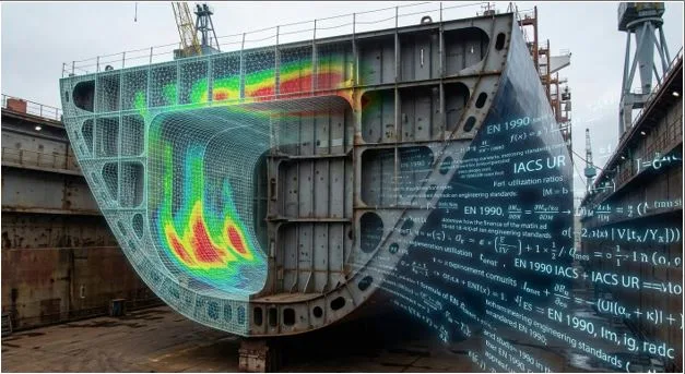
The solver runs the model overnight. The hardest part of the project to schedule starts after that: matching those results against code requirements and assembling the documentation that proves compliance. Most of the engineering hours in a verification scope go here, and so do most of the comments that come back from the reviewing body. Below we look at which of those operations FEA verification tools take over.
Where the time goes after the solve
A solver returns stress, displacement, and force fields. Design codes work in different quantities: section utilization ratios, buckling lengths, fatigue detail categories, and cross-section classes. Converting one into the other happens by hand. The engineer exports stresses to a spreadsheet, substitutes them into the code formulas, compares against allowables, and records the result.
Every one of those steps carries a small probability of error. On a single check, it is negligible. Across several hundred checks spread over a full model, the accumulated probability stops being negligible, and the error rarely announces itself. A buckling length assigned incorrectly, or an interaction check that was skipped, produces a plausible number that survives a quick review.
Checking every finite element under every load combination by hand is not physically possible. Selective checking follows from that.
The volume of combinations is set by the code text
EN 1990 sets the rules for combining actions. For fundamental ultimate limit state combinations, it gives expression 6.10, or the pair 6.10a and 6.10b, from which the less favorable governs. Permanent actions enter at 1.35 where unfavorable, the leading variable action at 1.5, and accompanying variable actions at that same factor further reduced by ψ0, which runs 0.7 for imposed loads in office areas and 0.5 for wind on buildings.
The multiplication comes from the leading-action role rotating. Each variable action takes that role in turn: wind from four directions, snow, temperature, imposed load, seismic and accidental scenarios, each one heading its own series of combinations. The procedure then repeats across the three serviceability combination classes (characteristic, frequent, quasi-permanent) and separately again for accidental and seismic design situations. Fifteen base load cases unfold into several hundred design combinations.
Three hundred and more combinations is routine volume for marine and heavy-lift structures. Sometimes the rules require it outright. IACS UR S34 defines the minimum set of load cases for finite element strength assessment of container ships, crossing draft condition, container weight, ballast and fuel tank state, and the sign of the still-water hull-girder bending moment. One clause covers multi-bay cargo holds specifically: each bay is modeled empty in turn as a load case of its own. All of that forms the minimum, on top of which wave-direction sensitivity is added.
At that volume, selective checking becomes a bet on engineering intuition. The governing combination can sit in a region of the load matrix nobody flagged as critical.
Element recognition and exhaustive checking
FEA verification tools such as SDC Verifier (https://sdcverifier.com/) ease the volume constraint: large sets of load combinations can be processed, with governing loads and results identified automatically. For every element and every check, the worst combination is recorded together with the utilization ratio it produced. The engineer sees the value and the conditions that produced it, which removes the manual back search through the load matrix.
A less obvious problem gets solved first. Code checks apply to members, panels, welds, and bolted connections. A finite element mesh contains none of those objects, so they have to be assembled from it. For a beam, collinear mesh elements merge into a single member, and only after that assembly do buckling length and slenderness carry physical meaning under EN 1993-1-1 or AISC 360. Group them wrong and the utilization ratio refers to nothing real.
Panels go through the same procedure. Shell fields between stiffeners are identified along with their dimensions, thickness, and edge restraints, all of which the plate buckling calculation under EN 1993-1-5 requires. Entered by hand, that geometry is typed panel by panel, and on a large model the input alone runs into days.
Weld recognition works from element connection nodes: flagged welds receive detail categories and the corresponding S-N curves.
A report is an interlocking package
The other half of the effort goes into documentation. A report is commonly pictured as a single file carrying final utilization ratios.
Indian Register of Shipping FEA guidelines, IRS-G-DES-05, revision 01 of December 2024, list what a submission has to contain:
- Structural drawings
- A model description covering every modeling assumption and every deviation from the drawings
- Plate thickness and profile section plots
- Boundary conditions
- All loading conditions reviewed, with calculated hull-girder shear force and bending moment distributions
- Confirmation that the applied loads are correct
- Von Mises and in-plane component stress fields
- Buckling utilization ratios for plates and stiffened panels
- Summary compliance tables
A separate line in the same list names the computer program used, including its version and date.
What that package contains determines what happens on any model revision. Change one plate thickness and, formally, everything has to be reconciled again: stresses, utilization ratios, compliance tables and conclusions. A stress extract sitting in a spreadsheet goes stale the moment geometry or boundary conditions change, and through iterative design it does not always get rebuilt. Decisions keep getting made on outdated numbers.
Rebuilding that package by hand costs weeks. A poorly structured submission with missing sections comes back for two or three revision cycles. Automated generation changes the economics of this stage: the document regenerates from the current state of the model in minutes, and the report version matches the analysis version by construction.
Code updates landing mid-project deserve separate attention. DNV-RP-C203, with its 2025 amendments, revised the S-N curves and added an appendix for large-diameter wind turbine support structures. Under a manual method, that means recomputing the fatigue check from scratch. Under an automated one, the formula library updates and the check runs again.
Where automation stops
Throughput improves on the operations that can be formalized: iterating combinations, substituting into code formulas, extracting governing values, and assembling documentation. Responsibility for the result stays with the engineer. NAFEMS puts the verification and validation position plainly: whoever performs the analysis answers for it, which makes understanding what the software actually does part of the job.
Choosing the analysis approach, assigning boundary conditions, handling singularities at concentration zones, judging mesh convergence and deciding whether a specific code clause applies to a specific detail: all of this remains a matter of engineering competence at any level of automation.
Why does this become a resource question
The workforce situation is what gives the shift its economics. EY reports roughly 679,500 engineering positions open across the United States as of April 2026, against about 141,000 engineering graduates entering the workforce each year, with nearly a quarter of civil engineers approaching retirement without prepared successors. There are no additional engineering hours available for manually reconciling results against codes.
Under that shortage, how the available hours get divided between analysis, checking, and documentation turns into a project decision.