Why Your Proximity Sensor Doesn’t Reach as Far as the Datasheet Says
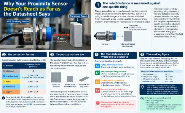
| An M18 inductive proximity sensor is specified at 8 mm. You mount it 6 mm from the target, which feels like a sensible margin, and it works on the bench.
On the machine it detects intermittently. Nobody has moved anything. The sensor isn’t faulty. The target is aluminium. The rated distance is measured against one specific thingThe sensing distance printed on an inductive sensor is measured under conditions defined by IEC 60947-5-2, using a standard target: a square plate of mild steel, 1 mm thick, with a side length equal to the sensor’s face diameter or three times the rated distance, whichever is larger. That’s the reference. Every published sensing distance is a statement about that plate. Inductive sensors work by generating a high-frequency field and detecting the eddy currents a conductive target induces in itself. How strongly that happens depends on the target’s electrical conductivity and its magnetic permeability. Mild steel is ferromagnetic, which makes it very good at absorbing energy from the field. Most other metals are not. So the same sensor sees different metals at different distances, and the differences are large. The correction factorsTypical reduction factors, relative to mild steel at 1.0: Stainless steel, roughly 0.70 to 0.85 depending on grade — austenitic grades like 304 and 316 are non-magnetic and sit at the lower end. Brass, roughly 0.40 to 0.50. Aluminium, roughly 0.35 to 0.45. Copper, roughly 0.30 to 0.40. These are indicative. The actual figure is a property of the specific sensor design and the specific alloy, and it belongs on the datasheet — manufacturers publish a correction factor table per series, and sensor manufacturers like GTRIC list them alongside the rated distance for each part, which is where the number for your combination should come from rather than from a rule of thumb. Run the earlier example. An 8 mm sensor against aluminium at a factor of 0.4 has a real sensing distance around 3.2 mm. Mounted at 6 mm, it isn’t marginal. It’s out of range, and the intermittent detection you’re seeing is the target wobbling at the very edge of a field that shouldn’t reach it at all. Target size matters as much as materialThe standard target is sized in proportion to the sensor. A target smaller than that reduces the sensing distance further, because less of it sits in the field. This catches people detecting small screws, thin sheet metal, or the edge of a component rather than its face. Thickness matters too for non-ferrous targets, where the eddy currents flow in a surface layer — foil-thin aluminium behaves differently from a solid block. The four distances, and which one to design toThe standards define a hierarchy that’s worth knowing because the words get used loosely. Sn, the rated operating distance, is the nominal catalogue figure. It includes no allowance for anything. Sr, the effective operating distance, is what an individual sensor actually achieves at 23 °C and rated voltage. It’s permitted to fall within ±10% of Sn, so unit-to-unit variation is built into the specification. Su, the usable operating distance, is Sr across the full rated temperature and voltage range. Another ±10% band. Sa, the assured operating distance, is the one to design against. It runs from 0 to 81% of Sn, and it’s the range in which any sensor of that type will detect the standard target under any permitted condition. 81% of nominal, before you apply the material correction factor. That’s the honest starting point. Working figureTake the rated distance. Multiply by 0.81 for the assured range. Multiply by the correction factor for your target material. Reduce further if your target is smaller than standard. Then mount at around half of what’s left. For an 8 mm sensor against aluminium: 8 × 0.81 × 0.4 gives about 2.6 mm assured, so mount at around 1.3 mm. That will look absurdly close to anyone used to thinking in terms of the catalogue number. It’s the distance at which the sensor will still be working in August, on the fiftieth machine, with a target from a different batch. If that gap isn’t mechanically practical, the answer isn’t to push the sensor further out and hope. It’s a longer-range variant, a larger barrel, or a mild steel target plate bonded to the aluminium part — which is a standard trick and much cheaper than a sensor that works four days a week. |